
This tutorial is based on Real-Time GPS Monitoring using M5Stick C (ESP32) with the help of Qubitro’s GPS Mapping System.

Things used in this project
| Hardware components | ||||
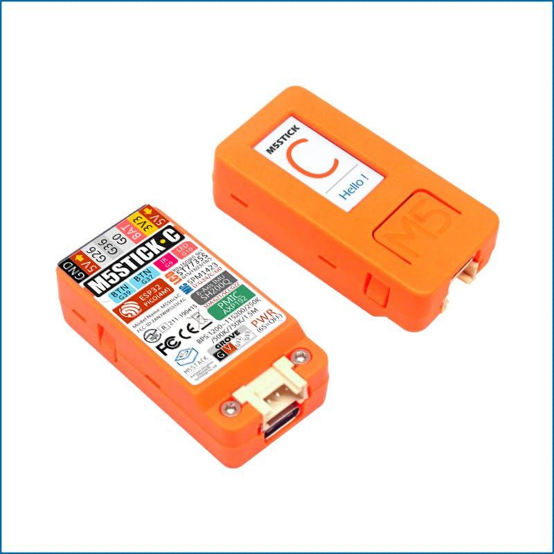 | M5Stack M5StickC ESP32-PICO Mini IoT Development Board | × | 1 | |
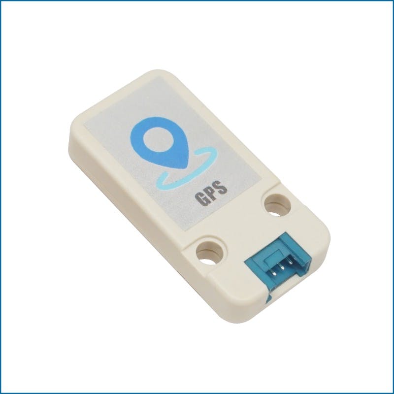 | M5Stack Mini GPS/BDS Unit | × | 1 | |
| Software apps and online services | ||||
| Qubitro | ||||
 | Arduino IDE | |||
| Google Colab |
Story
In this DIY tutorial, we are going to build an IoT-based GPS Location tracker using M5Stack GPS Unit and M5Stick C. Here, we have used Qubitro as a Cloud platform to Map the GPS Coordinates, and this coordinates will be mapped by using Google Colab with the help of simple python script.
Hardware Connections:
Just kidding, there is no hard-wiring in this tutorial, simply connect the GPS unit with M5StickC, that’s all.
Let’s Compile:
I used Tiny GPS library, It’s very simple to use with maximum GPS units, and all the Cloud Integration could be found in the Qubitro documentation page and upload the below Qubitro_Gps.ino sketch to the M5StickC.
#include <M5StickC.h>
#include <TinyGPS++.h>
#include <QubitroMqttClient.h>
#include <WiFi.h>
TinyGPSPlus gps;
HardwareSerial ss(2);
float Lat, Lng;
String  lat_str , lng_str;
int sat, battery = 0;
float b, c = 0;
// WiFi Client
WiFiClient wifiClient;
// Qubitro Client
QubitroMqttClient mqttClient(wifiClient);
// Device Parameters
char deviceID[] = "Qubitro-Device-ID";
char deviceToken[] = "Qubitro-Device-Token";
// WiFi Parameters
const char* ssid = "ELDRADO";
const char* password = "amazon1234";
void setup()
{
M5.begin();
M5.Lcd.setRotation(3);
M5.Lcd.fillScreen(BLACK);
M5.Lcd.setSwapBytes(true);
M5.Lcd.setTextSize(1);
M5.Lcd.setCursor(7, 20, 2);
M5.Lcd.setTextColor(TFT_GREEN, TFT_BLACK);
ss.begin(9600, SERIAL_8N1, 33, 32);
wifi_init();
qubitro_init();
}
void loop()
{
while (ss.available() > 0)
if (gps.encode(ss.read()))
{
if (gps.location.isValid())
{
M5.Lcd.setTextColor(RED);
M5.Lcd.setCursor(0, 0);
M5.Lcd.printf("</Qubitro Uplink Done/>");
Lat = gps.location.lat();
lat_str = String(Lat , 6);
Lng = gps.location.lng();
lng_str = String(Lng , 6);
sat = gps.satellites.value();
Serial.print("satellites found:  ");
Serial.println(sat);
Serial.print("latitude :  ");
Serial.println(lat_str);
M5.Lcd.setTextColor(TFT_GREEN, TFT_BLACK);
M5.Lcd.setCursor(0, 20);
M5.Lcd.printf("latitude : %s", lat_str);
Serial.print("longitude: ");
Serial.println(lng_str);
//*Just for example
Serial.print("Alt: ");
Serial.println(gps.altitude.feet());
Serial.print("Course: ");
Serial.println(gps.course.deg());
Serial.print("Speed: ");
Serial.println(gps.speed.mph());
Serial.print("Date: "); printDate();
Serial.print("Time: "); printTime();
M5.Lcd.setCursor(0, 40);
M5.Lcd.printf("longitude : %s", lng_str);
String payload = "{\"latitude\": " + String(lat_str) + ",\"longitude\":" + String(lng_str) + ",\"Battery\":" + String(battery) + ",\"satellites\":" + String(sat) + "}";
mqttClient.poll();
mqttClient.beginMessage(deviceID);
mqttClient.print(payload);
mqttClient.endMessage();
M5.Lcd.setCursor(0, 60);
M5.Lcd.printf("satellites : %d", sat);
M5.Lcd.print("||");
batteryLevel();
M5.Lcd.setCursor(95, 60);
M5.Lcd.printf("Bat : %d", battery);
M5.Lcd.print("%");
delay(5000);
M5.Lcd.setTextColor(TFT_GREEN, TFT_BLACK);
}
}
}
void wifi_init() {
// Set WiFi mode
WiFi.mode(WIFI_STA);
// Disconnect WiFi
WiFi.disconnect();
delay(100);
// Initiate WiFi connection
WiFi.begin(ssid, password);
// Print connectivity status to the terminal
Serial.print("Connecting to WiFi...");
while (true)
{
delay(1000);
Serial.print(".");
if (WiFi.status() == WL_CONNECTED)
{
Serial.println("");
Serial.println("WiFi Connected.");
Serial.print("Local IP: ");
Serial.println(WiFi.localIP());
Serial.print("RSSI: ");
Serial.println(WiFi.RSSI());
M5.Lcd.setTextColor(RED);
M5.Lcd.setCursor(0, 8);
M5.Lcd.printf("Network Connected");
break;
}
}
}
void qubitro_init() {
char host[] = "broker.qubitro.com";
int port = 1883;
mqttClient.setId(deviceID);
mqttClient.setDeviceIdToken(deviceID, deviceToken);
Serial.println("Connecting to Qubitro...");
if (!mqttClient.connect(host, port))
{
Serial.print("Connection failed. Error code: ");
Serial.println(mqttClient.connectError());
Serial.println("Visit docs.qubitro.com or create a new issue on github.com/qubitro");
}
Serial.println("Connected to Qubitro.");
M5.Lcd.setTextColor(RED);
M5.Lcd.setCursor(0, 25);
M5.Lcd.printf("Uplink Established");
mqttClient.subscribe(deviceID);
delay(2000);
M5.Lcd.fillScreen(BLACK);
}
void batteryLevel() {
c = M5.Axp.GetVapsData() * 1.4 / 1000;
b = M5.Axp.GetVbatData() * 1.1 / 1000;
//  M5.Lcd.print(b);
battery = ((b - 3.0) / 1.2) * 100;
if (battery > 100)
battery = 100;
else if (battery < 100 && battery > 9)
M5.Lcd.print(" ");
else if (battery < 9)
M5.Lcd.print("  ");
if (battery < 10)
M5.Axp.DeepSleep();
Serial.print("battery: ");
Serial.println(battery);
}
void printDate()
{
Serial.print(gps.date.day());
Serial.print("/");
Serial.print(gps.date.month());
Serial.print("/");
Serial.println(gps.date.year());
}
// printTime() formats the time into "hh:mm:ss", and prints leading 0's
// where they're called for.
void printTime()
{
Serial.print(gps.time.hour());
Serial.print(":");
if (gps.time.minute() < 10) Serial.print('0');
Serial.print(gps.time.minute());
Serial.print(":");
if (gps.time.second() < 10) Serial.print('0');
Serial.println(gps.time.second());
}
Data Visualization:
Once you upload the code to M5Stick C, go to your Qubitro Device Portal and you can see the create a chart tab.

Qubitro Device Page
After clicked the Creation a Chart tab, select chart type as map and select the data variables ( like longitude, latitude as per the tabs)

Create a Chart (Map) page
That’s all, now you are good to go, navigate to the Analytics area, and you can see the uploaded GPS Co-ordinates are mapped.

Mapped Co-ordinates
Mapping with Google Colab:
If you want to map your whole location data, here I’m used python script which can phrase GPS co-ordinates and map. First you have to download the Data from Qubitro Portal by the format of CSV (now in Beta Stage), then log in to google colab and import the below python script.

Import the downloaded CSV files from the Qubitro Portal. Execute the blocks one by one (make sure to rename the files in both script and files).

So it’s very simple and easy to use python script, Once you executed the final block you can find the logged map (sample CSV file uploaded in the GitHub).

Device in action
Code
Qubitro GPS Mapping
# import libraries + wardriving data

import pandas as pd
wd = pd.read_csv ('Neo-Baby-Walk.csv') # import list of all GPS Data from CSV file to pandas data frame
wd.sample(100) # sample 10 random devices from dataset

# len(wd) # number of detected devices

# start mapping devices

import folium
from folium import Map, Marker
basic_map = folium.Map(location=[33.675899,-117.602236	],zoom_start=17) # manually pick scope of map
folium.PolyLine(wd[['Latitude', 'Longitude']].values.tolist(),line_opacity = 0.5, weight = 4).add_to(basic_map) # plot route
display(basic_map)